
As you know, a modern car contains a large number of auxiliary systems that facilitate the vehicle control for drivers. And almost all of these systems have electronic control units which are small computers for performing a certain narrow range of tasks for monitoring certain systems. For their proper operation, stable power supply is required which is directly related to the operation of the alternator. Despite the fact that the modern automotive alternator has a fairly advanced design, worked out over several decades, however, it also often needs to be repaired for one reason or another.

Alternator LR-160 14V 60A Hitachi
1 – rotor; 2 – stator; 3 – pulley; 4, 7 – ball bearings; 5 – fans; 6 – rectifier unit; 8 – voltage regulator with a brush holder; the arrows indicate the direction of flow of the cooling air.
Let’s consider what are the main failures symptoms of alternators and how they can be detected most simply. So, here is a list of the main car problems in the alternator operation:
- poor contact between the brushes and slip rings;
- breakage or interturn closure of the excitation winding, as well as its closure to the rotor;
- breakage of one of the stator winding phases;
- short circuit of the stator winding to the core or its interturn short circuit;
- breakdown of diodes of the rectifier bridge.
Let us consider the alternator diagnostics using the test bench MS002 COM.
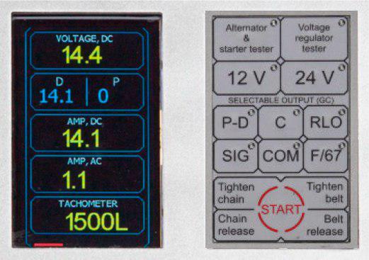
Control panel and information display of the test bench MS002 COM
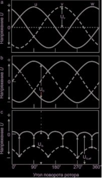
It worth paying attention to the AC indicator "AMP, AC" in the figure above, it indicates the presence of harmonics in the output circuit of the alternator. As can be seen from the following figure, the alternating voltage is almost levelled with a voltage of the alternator by means of the rectifier unit. However, a small part of the AC voltage remains, the so-called presence of harmonics.
It means that the actual voltage of the alternator is different from the voltage of the on-board network. The correlation is fair: harmonics of alternator effective voltage ∙ 0.04. This rule can also be applied to the alternator current.
Thus, when diagnosing, pay your attention to the indicator of constant "AMP, DC" and alternating current "AMP, AC". The ratio should be observed: the alternating component of the alternator current must be less or equal to 10% of the direct current. The harmonics will be present if the diode has an open or short circuit in one of the stator windings. Therefore, the presence of harmonics is used for troubleshooting.
An open circuit of the diodes can be easily detected in the following way: you should start the alternator on the test bench at medium speed (about 1500 rpm) and check the value of alternating current in the alternator load circuit. The alternating component magnitude of the load current can be drawn conclusions about the cause of the fault. This value should not exceed 10% of the load current constant component. For example, if the load current is 40 A, then the alternating component should not exceed 4 A. With the oscilloscope you will draw the same conclusions if you connect its measuring probe to the output of the alternator "B +". In this case the ripple value of the rectified voltage will also indicate a problem with the diode bridge.
2. Interturn closure of the stator winding, or the closure of one of the phases to the alternator housing
Under this fault the value of the alternating component of the rectified current will be from 40% to 50% of the value of the constant current load. The inter-turn short circuit as well as the short circuit of the stator winding to the case leads to an insufficient charge of the car battery and to the heating of the alternator which, in its turn, can cause further destruction of the insulation of the stator winding and premature failure of the alternator bearings.
In some cases in order to exclude a malfunction of the voltage regulator, it is possible to test the operation of the alternator without the relay itself. Not any alternator construction allows such testing but when there is a convenient access to the slip rings of the alternator rotor, this test is possible. In this case the power to the rotor should be supplied directly from the alternator output ensuring contact of the rings with the "B +" and "B-" outputs of the alternator. When performing this testing, the alternator speed should be increased smoothly, carefully watching the voltage at the output terminals of the alternator. At about 600 rpm (depending on the alternator type, the speed value may differ) this alternator voltage will be about 15 V. As before, the absence of the alternating component of the load current will indicate that the stator / rotor windings and the rectifier bridge are in good condition. It is not recommended to increase the alternator speed, since a further increase in the generated voltage can damage the elements of the rectifier bridge.
Conclusions
A modern car has a large number of consumers of electrical energy and, therefore, the load current of alternators can reach 150 A or more. But in order to identify the above failures, it is enough to check the alternator with a load current of up to 50 A. Thus, if in the course of this testing the alternator provides a stable voltage about 14.5 V or corresponding to the set one, and if there is no ripples of the rectified voltage and the variable component is within the permissible 10%, then we can say that the alternator is under operation and can be installed back on the car.
COMMENTS